
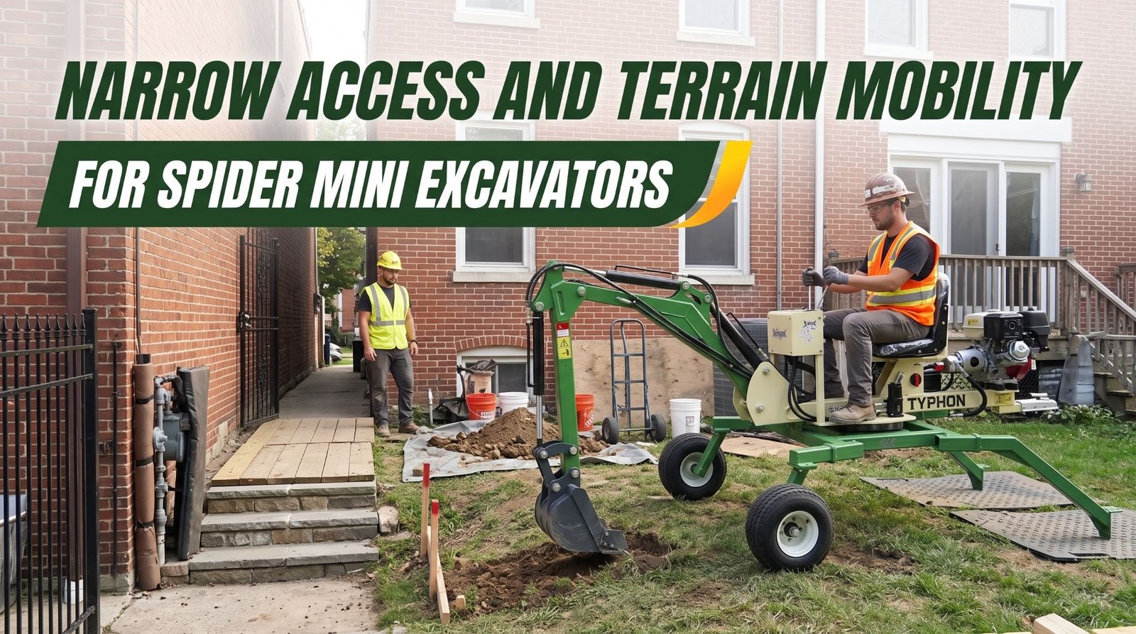
Narrow Access and Terrain Mobility for Spider Mini Excavators
Restricted access and uneven ground can complicate excavation projects in historic neighborhoods, residential yards, and confined construction sites. Although spider mini excavators are designed for narrow passages and challenging terrain, measuring only the entrance gate can overlook obstacles such as utility meters, protruding pipes, low windows, and changes in ground level. Accurate route assessment helps prevent equipment damage, surface disturbance, and unnecessary repositioning.
Machine mobility depends on its travel configuration, overall dimensions, ground clearance, support-leg design, and the traction available on the surface. A mounted bucket or attachment may extend beyond the tracks, while wet clay, steep slopes, and steps can affect movement and stability. Comparing the entire travel route with the manufacturer’s dimensional and operating requirements helps determine whether the machine can pass safely and where additional access preparation may be needed.
Before moving into a confined work area, crews should measure the narrowest clearance, identify overhead and underground hazards, and assess steps, slopes, and ground conditions. Approved ramps, ground protection mats, suitable barriers, and a trained spotter can help manage specific access risks when used according to site conditions and manufacturer guidance. Once inside, planning setup positions within the machine’s permitted working limits helps reduce excessive reach, repeated repositioning, and delays during excavation.
Maneuvering in Restricted Spaces
Getting through the entrance is only part of the challenge. Once inside a confined area, the machine still needs room to travel, turn, and work near walls, fences, plants, and people. Careful route planning and slow, controlled steering help prevent collisions and damage in tight spaces. Before moving, walk the planned route and identify obstacles, overhead restrictions, and nearby structures. Determine where the machine can turn safely, and plan the movements to avoid reversing through long, narrow passages. If turning space is unavailable, consider whether the machine can enter, complete the work, and exit along the same path.
Travel at a slow, steady speed and use small, gradual steering movements instead of sharp corrections. Stop before making adjustments that bring the machine close to walls or other obstacles. Pivoting a tracked machine in place can cause the rear section, folded boom, or attachment to strike nearby objects and damage finished surfaces. Check the clearance around the entire machine, not just the tracks, because the counterweight, folded legs, and attachment may extend beyond them. Keep the boom and attachment in the manufacturer’s recommended travel position, and check overhead clearance before raising the boom or adjusting the legs near roofs, windows, or tree branches.
Operator awareness is essential when moving through narrow passages. Use a trained spotter when the operator cannot see both sides of the machine clearly. Position the spotter where they can monitor the narrowest passage, agree on hand signals or radio communication before moving, and stop immediately if the spotter signals or becomes difficult to see. Keep other people away from the travel path and pinch points between the machine and fixed objects.
Confined areas also concentrate the machine’s swing path. Before digging, confirm the upper structure and boom can rotate through the planned working arc without striking walls or fences. Mark the swing radius and keep workers on foot outside it.
Key takeaway: Plan travel routes and turning areas in advance, steer slowly with small inputs, watch the full machine envelope, and use a trained spotter wherever clearance is limited.
Machine Dimensions and Access Clearance
A spider excavator’s dimensions determine whether it can pass through narrow gates, pathways, and restricted entrances. Checking the machine’s actual size and the full access route helps prevent damage and ensures safe movement into the work area.
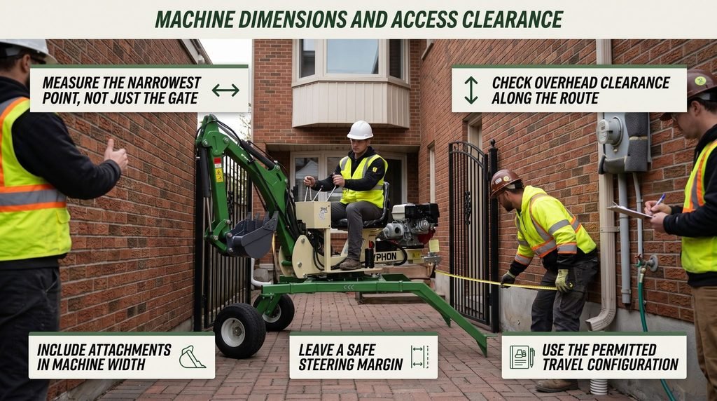
- Minimum Travel Width: Check the manufacturer’s dimensions for the narrowest travel configuration, including leg and track positions.
- Overall Height and Length: Confirm the machine’s travel height and folded length, including the boom, arm, cab, mirrors, and other mounted equipment.
- Attachment Clearance: Account for buckets, thumbs, couplers, and other attachments that may extend beyond the machine’s main dimensions.
- Route Measurements: Measure the entire access path at its narrowest points and check overhead obstacles such as eaves, tree branches, and utility lines.
- Clearance and Obstacle Protection: Allow extra room for steering and uneven ground. Remove attachments or approved obstacles when necessary, and protect nearby structures and utilities from contact.
Key takeaway: Compare the machine’s actual width, height, and length in its real travel configuration, including attachments, with the narrowest and lowest points along the full access route, and leave a margin for safe steering.
Mobility Across Uneven Terrain
Some spider mini excavators are built specifically for difficult ground. Depending on the design, their legs can be raised, extended, and angled independently, which lets the machine adapt to steps, terraces, banks, and irregular surfaces that would stop a conventional machine. Some models can travel on wheels or tracks while adjusting their legs to keep the upper structure level. These capabilities open up hillside lots, wooded slopes, and terraced gardens to mechanized excavation.
Actual capability depends on the model, its configuration, its slope limits, and the manufacturer’s operating instructions. Two machines that look similar may have very different permitted slopes for travel and for work. A single machine may also have different limits depending on direction of travel, leg position, and attachment. Review those limits before the job, and treat them as fixed boundaries rather than rough guides.
Uneven terrain changes the machine’s balance with every move. When one support climbs onto a rock or terrace edge, weight shifts to the other supports. On a slope, the downhill supports carry more of the machine’s weight. Move deliberately, one adjustment at a time, and keep the upper structure as level as the manufacturer requires during travel. Where the manufacturer permits travel on inclines, moving straight up and down is generally more stable than moving across the slope. Avoid turning on inclines whenever possible.
Obstacles such as steps, curbs, and terrace walls need particular care. Follow the manufacturer’s procedure for crossing them, if that model permits it at all, and never improvise a climbing method. Where steps or drops are too high or the surface is fragile, build a temporary ramp from timber mats or move the machine by another route. Check the condition of each feature before crossing, since old masonry steps and retaining walls may not carry concentrated loads.
When the terrain falls outside the machine’s limits, choose another approach. That may mean a different setup point, a reconfigured route, hand excavation for part of the work, or a different machine. A slower plan is always better than pushing equipment past what it was designed to do.
Key takeaway: Specialized support systems help spider excavators handle irregular ground, but actual terrain capability depends on the model, its configuration, slope limits, and the manufacturer’s operating instructions.
Ground Contact and Traction
Tracks, wheels, support legs, and foot pads determine how a spider excavator moves and how it holds its position. Each configuration interacts with the ground differently. Tracks spread weight over a longer contact area. Wheels can roll efficiently on firm surfaces. Foot pads concentrate the machine’s weight onto small points when it’s set up to work. Knowing which components carry the load during each stage of the job helps you predict how the ground will respond.
Surface conditions have a direct effect on traction and support. Mud and wet clay can coat tracks and wheels and turn a gentle slope slick. Loose gravel and crushed stone can roll under tracks and reduce grip, especially on inclines. Saturated soil loses strength, and recent backfill over trenches and utility lines may compress under a concentrated load. Steep surfaces combine all of these effects, since gravity pulls the machine downhill while grip decreases.
Assess conditions before every travel move, not just at the start of the day. Walk the route and probe questionable areas with a soil probe or steel bar. Look for standing water, sunken strips that point to old trenches, and soft spots in lawns and planting beds. Ask the property owner about septic systems, drain fields, buried tanks, and irrigation lines, and contact your local utility locating service before any digging. Reassess after rain, since a route that was firm in the morning can soften by afternoon.
Protect traction and the surface at the same time. Lay ground protection mats or timber mats across soft ground, lawns, and finished surfaces. Use approved load-spreading pads under foot pads where soil strength is uncertain. Keep tracks and wheels clean of packed mud, and check track tension and tire condition according to the manufacturer’s schedule, since worn or loose components reduce grip. If a track slips or the machine begins to slide, stop traveling at once. Lower the bucket to the ground where that adds support, and reassess before moving again.
Key takeaway: Tracks, wheels, and support legs each meet the ground differently, so assess mud, loose gravel, wet soil, and slopes before travel, and use mats and load-spreading pads to protect traction and support.
Positioning for Efficient Excavation
On a restricted site, every repositioning move costs time and briefly reduces stability. Correct positioning lets the boom and arm reach the required digging area from as few setups as possible. It’s the point where good mobility planning turns into real productivity.
Plan the machine’s location around the excavation layout. Stake or paint the footings, trench lines, or pit outlines first. Then compare that layout with the manufacturer’s working range diagram, which shows maximum reach, digging depth, and dump height. Choose setup points that place most of the work within comfortable reach rather than at full extension. On a long trench or a scattered footing pattern, two or three well-chosen setups usually produce better accuracy and stability than one setup that requires overreaching.
Every setup point must also meet stability and clearance requirements. Place each support on firm, tested ground, away from excavation edges, soft spots, and loose rock. Spread the legs as wide as the space allows and the manufacturer permits, and level the upper structure within its working limits. Confirm the boom can swing through the planned arc without striking walls, fences, eaves, or tree limbs. In tight yards, the space available for leg spread may limit how much the machine can safely handle, so match the work to that stance.
Plan spoil handling with the setup. Identify where excavated material will go before digging begins, ideally on stable ground uphill of the machine or to the side, and well away from excavation edges. On restricted sites, spoil may need to go onto tarps, into a dumper, or into bulk bags for removal. A spoil location the machine can reach without repositioning saves time on every cycle.
When repositioning is necessary, treat it as a planned move. Lower the bucket, retract the boom into its travel position, walk the new location first, and move in short, controlled steps. Re-level and confirm stability before resuming work.
Key takeaway: Plan setup points around the excavation layout and the machine’s working range, so the boom and arm reach the digging area efficiently while each position keeps suitable clearance and stability.
Transport and Site Preparation
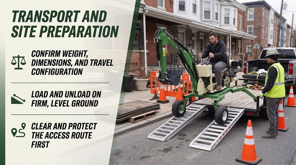
Many access problems can be solved before the machine leaves the yard. Confirming the machine’s dimensions, weight, loading requirements, and permitted travel configuration helps prevent unexpected obstacles at the jobsite. Preparing the access route in advance also protects the equipment and surrounding property while keeping the work on schedule.
Verify the machine’s weight in its actual configuration, including attachments, and compare it with the trailer’s rated capacity and the towing vehicle’s limits. Check the overall transport height against bridges, overhead wires, and low tree branches along the route. Secure the machine using the manufacturer’s designated tie-down points and follow the travel configuration specified in the operator’s manual.
Plan loading and unloading on firm, level ground away from traffic. Ensure the ramps are secure and rated for the machine’s weight and contact configuration. Follow the manufacturer’s ramp procedures, as some spider excavators require specific leg or wheel positions during loading. Keep everyone clear of the trailer and ramps, and use a trained spotter to guide the movement. If unloading takes place on a public street, coordinate with the property owner and check local permit requirements for temporarily blocking parking spaces or sidewalks.
Check the load-bearing capacity of driveways, walkways, patios, and other surfaces along the route. These areas may not support the concentrated loads of heavy equipment. Septic tanks, drain fields, cisterns, shallow utilities, and suspended decks may have strict weight limits or require engineering approval before equipment can cross them. Avoid restricted areas where possible, and use suitable ground protection mats when crossing is necessary and permitted.
Clear tools, planters, hoses, furniture, and debris from the access path before the machine arrives. Trim low branches where permitted, secure gates fully open, and protect meters, downspouts, and other fixed features near the route. Mark narrow passages and turning points with flags or other visible indicators so the operator and spotter can follow the same plan. Record route measurements and site conditions in the job file, and brief the crew on the access plan before moving the machine.
Key takeaway: Confirm the machine’s dimensions, weight, loading requirements, and travel configuration before transport, and clear and protect the access route to reduce delays and prevent damage.
Conclusion
Narrow access and terrain mobility make spider mini excavators a strong choice for restricted-site work, and the crews that get the most from them treat access as part of the job plan rather than an afterthought. Comparing the machine’s real dimensions, including attachments, with every pinch point along the route keeps it moving without contact. Slow, deliberate maneuvering with a trained spotter protects structures and people in tight spaces. Respecting each model’s terrain and slope limits keeps uneven ground from becoming a hazard, while careful attention to mud, loose gravel, and soft soil protects traction and support. Setup points planned around the excavation layout cut repositioning and keep every cycle within comfortable reach, and confirming transport details and preparing the route ahead of time prevents delays before the first cut. Before your next restricted-access job, walk the full route with a tape measure, check every figure against the manufacturer’s travel configuration and slope limits, and plan your setup points so your spider excavator reaches the work safely and finishes it efficiently.
Frequently Asked Questions
What makes spider mini excavators useful in restricted areas?
Spider mini excavators are useful in restricted areas because their compact configurations and specialized support systems help them access locations where larger machines may not fit. Depending on the model, narrow travel widths and repositionable support legs can help the machine pass through gates and adapt to uneven working surfaces. These features make them suitable for landscaping, slope maintenance, and excavation in confined spaces. Operators must still confirm the machine’s dimensions and operating limits before entering a restricted area.
What should be checked before entering a narrow access route?
Before moving through a narrow access route, check the machine’s overall dimensions with its attachments, the width of the entrance, the narrowest points along the path, and available overhead clearance. Also assess turning space, surface condition, slopes, and the route’s load-bearing capacity. Measure the entire route rather than relying only on the gate width, since walls, corners, and obstacles may restrict movement farther along the path. Plan a clear route before moving the machine.
Can every spider mini excavator operate on steep terrain?
No. A spider mini excavator’s ability to work on steep terrain depends on its model, configuration, support system, ground conditions, and manufacturer-specified operating limits. Some machines are designed for challenging slopes, but this does not mean they can safely operate on every incline or surface. Operators should consult the operator’s manual for separate limits covering travel, digging, and machine positioning. Unstable soil, loose material, and poor support can increase the risk of slipping or tipping, even when the machine is designed for sloped terrain.
How does positioning improve productivity?
Correct positioning helps the boom and arm reach the excavation area efficiently while reducing unnecessary travel and repeated machine setups. Placing the excavator on suitable ground with adequate support allows the operator to work within a more consistent range and maintain better control over digging depth and bucket placement. Planning the working position before excavation begins can also reduce repositioning time and disturbance to nearby surfaces. Stable positioning supports both productivity and digging accuracy, provided the machine remains within its operating limits.